
Principles of Design
In district heating systems, in which transmission and distribution lines are created by using pre-insulated pipes, all design and installation applications must be carried out in accordance with the standard TS EN 13941. As Yalçın Boru, our project department can provide all necessary support in order for your applications to comply with this standard and at the same time, to be beneficial both technically and economically at an optimum level.
For the control of the project designing, the following information must be obtained at the initial stage:
Temperature values (design, installation, operation),
Design pressure values,
Fluid flow rate,
Pipe diameter and quantities (diameter selection can also be made by Yalçın Boru upon request),
Conditions of the installation site (information about the excavation & filling area or console details if it is a gallery system),
In the light of this information, it can be checked whether the design conditions of your project comply with the standard TS EN 13941.
It is checked to which one of the project classes specified in the standard your project belongs, and the limitations are determined accordingly.
Class A project: These are the systems comprising pipes with low axial stress,
Pipes with small and medium sized pipe diameters,
And pipes with low risk to harm people and environment or give damage to buildings in the vicinity.
Class B project: These are the systems comprising high axial stress,
Pipes with small and medium sized pipe diameters,
And pipes with low risk to harm people and environment or give damage to buildings in the vicinity.
Class C project: These are the systems comprising pipes with large diameters and high pressure pipes,
Special and complex structures,
And pipes with high risk to harm people and environment or give damage to buildings in the vicinity.
The chart below is used to determine the limits according to the project classes generated.
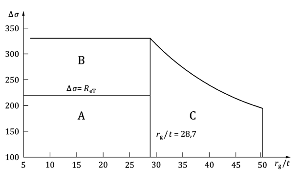
Axis Y represents axial stress, axis X represents the ratio of the radius and thickness of the carrier pipe.

∆T represents the difference between the fluid operating temperature and the ambient temperature during installation.
E elasticity module is taken as 210.000 MPa in general.
α expansion coefficient is taken as 1.2 x 10⁻⁵ in general.
Boundary lines are prepared in accordance with the standard pipe type specified in TS EN 253, and the boundary separating the zones A and B corresponds to a temperature of 85 °C. The boundary between the zones A and B and the zone C corresponds to the DN300 steel pipe.
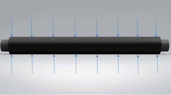
The Stress and Friction on the Pipe Wall
Generated by the inner pipe pressure on the pipe wall:
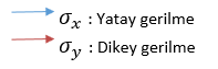
Vertical Stress
YHorizontal Stress
p: Inner pressure (MPa)
d: Outer diameter of the carrier pipe (mm)
 :Effective wall thickness (After deduction of negative tolerance and corrosion, mm)
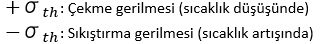
Stress due to temperature changes in the pipeline compared to the field application temperature:

Equivalent stress in the pipe:
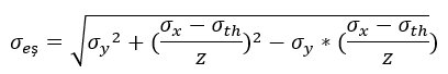
Z :Welding factor (taken in the range of 0.5-1, based on the NDT conditions of field welds)
The acceptable stress magnitude can be calculated by dividing the yield point of the carrier pipe by the safety factor.

 : The permitted carrier pipe stress value
 : Yield point of the carrier pipe (235 MPa in accordance with the type of carrier pipe in the standard TS EN 253)
 : Safety factor (can be taken as 1.5)
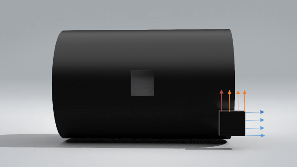
Friction Force
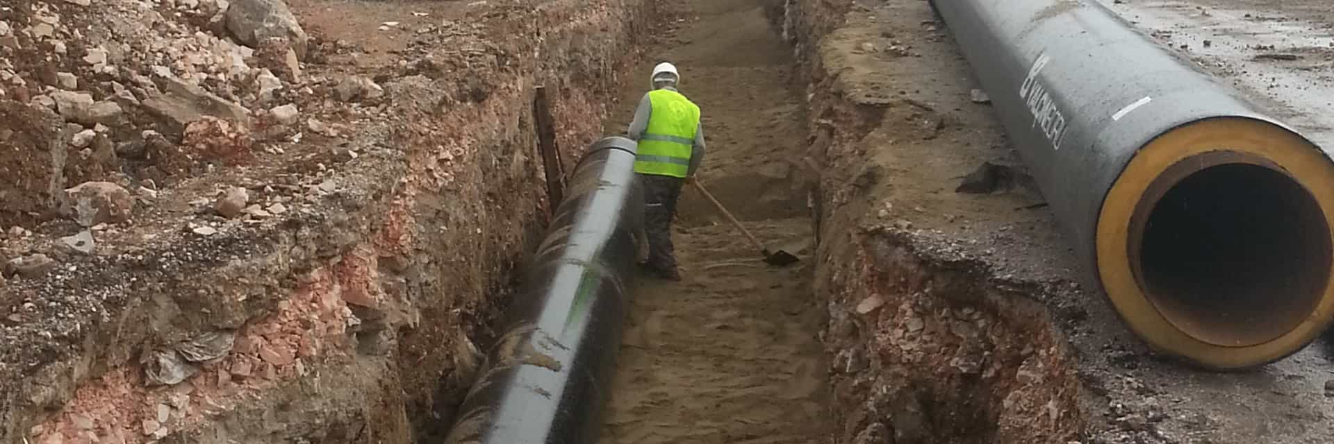
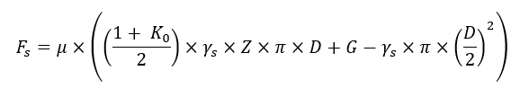
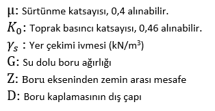
Pre-insulated pipe systems consist of carrier pipe, polyurethane insulation and HDPE casing pipe being connected to each other, and by means of this bond, the axial movement of the steel pipe as a result of expansion is limited with the contact of the outer surface with the soil in buried systems. The friction force occurring between the HDPE casing pipe and the environment of burying can be calculated with the formula given below:
Friction Distance, Axial Stress and Elongation Quantity
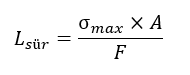
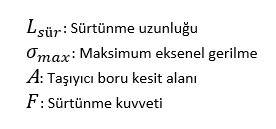
Finding the friction distance, which is the distance from the zero point to the point at which the maximum axial stress will occur, is an important value for performing the expansion and stress analysis in the pipe system and for determining how and in which positions the associated measures will be taken.
At this distance, the axial stress and expansion are partially controlled by the friction force.
This value can be determined with the formula given below:
By comparing the L length of the line with the Lfri length, it is determined how to find the axial stress;
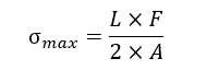
When L length is examined, if;  then, the maximum axial stress is:

If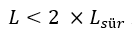 then, the maximum axial stress is:
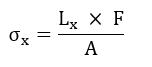
To determine the axial stress at a certain Lx point on the line;
If then, the axial stress on that point is:
If then;
then;

In addition to these, it is necessary to examine the status of prevention of elongation of the pre-insulated pipes buried under the ground by the friction force of the earth. Expansion elongation of pipes that are not buried, that go in the gallery, or in open condition:

On the other hand, the pipe expansion elongation buried under the ground is;

Taking Stress and Expansion under Control
Certain methods can be applied for controlling the stress & expansion impacts of the buried pre-insulated pipelines:
1. Without taking any measures for stress,
2. With turns in the forms of L – Z – U on the line,
3. With the use of compensator.
Installation without taking any measures for stress
Taken from the standard TS EN 13941 as mentioned in the first chapter and as can be seen with the diagram where the project categories are determined, the pipe systems can be installed without taking any measures as long as the maximum stress value of the pipe systems up to the diameter DN300 (in accordance with the standard TS EN 253, including DN300) does not exceed the value of 334 Mpa.
The most important aspect for these and other items is the burial of the pre-insulated pipe system in compliance with the instructions and standard values during the excavation & filling process.
Note: In this type of installation, although it is not recommended at the end of each one of the Lsür lengths, fixed support can be manufactured. In general, fixed supports are used in areas close to the building entrance. Control of the stresses with natural fixed point formation is a more appropriate method
Installation with Turns in the Forms of L – Z – U
Even if the project conditions are evaluated and it is determined that the maximum stress value remains in the safe zone, in some cases it may be preferred to have the stress fixed to a lower level. In these cases, the pipeline can be fixed at the desired stress level by placing the compensators or L – Z – U elements on the pipeline.
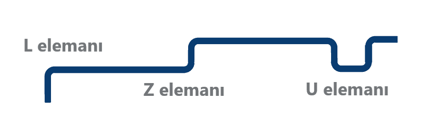
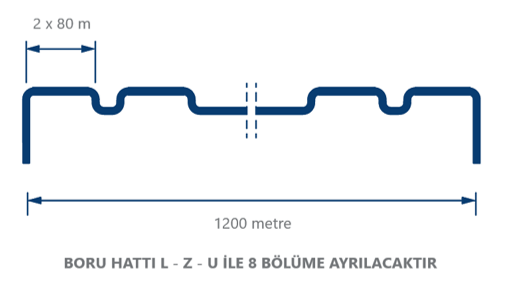
For example, in a straight and long pipeline, the distance required to achieve the desired stress value is determined. Along this line, the stress is always kept at the desired value by placing one of the L – Z – U elements at every 2 x L distance. To give a simple example, let us assume that the stress value of a line with a length of 1200 metre is preferred to be kept at 150 MPa, and the length of the line at which 150 MPa stress will occur is 80 metres. According to this, as can be seen with the figure below, an L – Z – U element must be used at every 2 x L distance (maximum). 1200 / (2 x 80) = 7,5; which means there must be 8 districts.
Installation with the use of compensator
Just like the elements L – Z – U, if the stress value of the pipeline is to be kept at the desired level, this can also be enabled by using compensators.

Since the pre-stressed compensator is used, the amount of elongation affecting the compensators must be known and a compensator in the expansion class suitable for this must be selected. For this:

If the distances in the two directions of the compensator are equal, this value is multiplied by two. If they are different, they must be calculated separately.
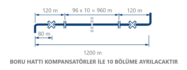
For example, the stress value of a straight line with a length of 1200 metres between two elbows is wanted to be kept at 150 MPa. For 150 MPa, we assume that the required L length is 80 metres (the distance where a natural fixed point is formed) and the distance between both compensators is 96 metres. 1200 – (2 x 80) = 1040 this is the total distance where the compensators will be placed, and 1040 / 96 ≈ 11 sections must be created. One of these sections is reduced to 10 sections by placing a compensator half the distance of the compensator from the natural fixed points.