

Choosing the right pipe diameter is one of the most important aspects of projects such as water transmission lines and heating lines. As Yalcin Boru, we provide consultancy on the selection of the appropriate pipe diameter for the healthy operation of the systems designed by our customers, as well as the optimisation of initial investment and operating costs.

With the above formula, the required flow rate can be calculated according to the return and return temperatures of the water.
Symbols and units are described below.
m (m3/s) : Water flow rate
Q (kW) : Heat Requirement
ρ (kg/m3) : Fluid mass
Cp (kj/kg ˚C) : Fluid specific heat
∆T (˚C) : Temperature difference between return and return water
As a result of the flow rate calculation, the fluid velocity can be calculated with the following formula by selecting a suitable pipe diameter.

The above formula gives us the fluid velocity and its symbols and units are described below.
V (m/sn) :Fluid velocity
Diç(m) : Carrier pipe inner diameter
After obtaining the fluid velocity, it is necessary to calculate the Reynolds Number, which will give us an idea about the flow characteristics in the pipe.

The explanations and units of the symbols in this formula are as follows:
Re : Reynolds number
μ (cP) : Fluid dynamic viscosity
The sample table containing the values of water changing depending on the temperature is as follows;
|
Temperature (˚C) |
Density (kg/m3) |
Dynamic Viscosity (Ns/m2) x 10-3) |
Specific Heat (Kj/Kg ˚C) |
Specific Volume (m3/kg) |
|
0 |
1000 |
1,787 |
4,210 |
0,001000 |
|
5 |
1000 |
1,519 |
4,204 |
0,001000 |
|
10 |
1000 |
1,307 |
4,193 |
0,001000 |
|
20 |
998 |
1,002 |
4,183 |
0,001002 |
|
30 |
996,02 |
0,798 |
4,179 |
0,001004 |
|
40 |
992,06 |
0,653 |
4,179 |
0,001008 |
|
50 |
988,14 |
0,547 |
4,182 |
0,001012 |
|
60 |
983,28 |
0,467 |
4,185 |
0,001017 |
|
70 |
977,52 |
0,404 |
4,191 |
0,001023 |
|
80 |
971,82 |
0,355 |
4,198 |
0,001029 |
|
90 |
965,25 |
0,315 |
4,208 |
0,001036 |
|
100 |
957,85 |
0,282 |
4,219 |
0,001044 |
Table 1 : Physical Properties of Water
After the Reynolds number, we need to find the "Relative roughness" number, which is the last data required to calculate the friction loss caused by the current assumptions.

The units and symbols in this formula:
εb :Relative roughness
ɛ (m) : Carrier pipe roughness coefficient
The results found are sufficient to find the coefficient of friction in the current flow. "Moody Diagram" is used to determine this coefficient.
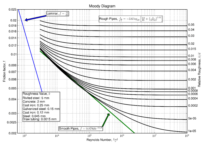
Figure 1: Moody Diagram
The pressure loss of the line is calculated with the friction coefficient (f) obtained from the diagram.
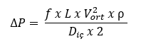
∆P (N/m2) :Pressure decrease
L (m) : Length of the line
ρ (kg/m3) : Fluid Specific Gravity
In the values found, the flow rate and friction pressure are evaluated together, if the speed value and friction pressure are not suitable for the type and needs of the projected system, the calculation can be repeated by changing the diameter selected at the beginning of the calculation.
If you wish to confirm the pipe diameter selections made during the project design phase, Yalçın Boru's expert Project Department will be pleased to assist you.
